
Johnson prem B
Design Engineer Associate
Precision CAD design for real mechanical products.
Skills & Tools
- PTC CreoPTC Creo
- SolidWorksSolidWorks
- AutoCADAutoCAD
- Fusion 360Fusion 360
- Ansys WorkbenchAnsys Workbench
- WindchillWindchill
About Me
I am Johnson Prem B — a mechanical design engineer and design engineer associate working across CAD modelling, mechanical assemblies, product configuration and engineering documentation that moves cleanly from concept to manufacture.
Work Experience
Feb 2026 - Present
Design Engineer Associate
CADOpt Technologies
Work on mechanical CAD design and engineering data management activities.
Create and modify 3D CAD models and mechanical assemblies using Creo and other CAD tools.
Work with Windchill for CAD data management and product configuration activities.
Support BOM management, CAD restructuring, and engineering documentation.
Work with Windchill Options & Variants, including options, choices, rules, and variant specifications.
Support configurable product structures and product configuration activities.
Review CAD data and identify design and structural issues during engineering workflows.
Prepare and maintain engineering documentation related to CAD and product data.
Collaborate with engineering teams to support design changes and project requirements.
Apply mechanical engineering principles to CAD design and product development activities.
July 2024 – August 2024
Intern
KWALITY Coil Products
Studied oilcell quality inspection procedures and applicable standards.
Participated in quality control activities and professional inspection sessions.
Supported quality-related documentation and reporting.
Gained practical exposure to engineering quality and inspection procedures.
Observed inspection practices and quality requirements applicable to engineering products.
Education
2022-2025
B.E. Mechanical Engineering
Latha Mathavan Engineering College
2019-2021
Diploma in Mechanical Engineering
St. Joseph’s Polytechnic College
Selected Work
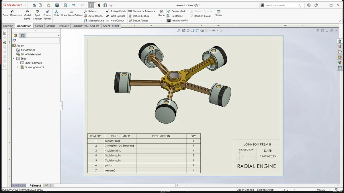
Radial Engine Assembly
SolidWorks
A college project recreating a radial engine as a production-style assembly. Each piston, ring, pin and bearing was modelled as an individual part, constrained onto the master rod and crank structure, then presented on a drawing sheet with a numbered bill of materials.
Objectives
Model every engine component as a separate, editable part
Fully constrain the radial assembly on the master rod
Produce a drawing sheet with a numbered bill of materials
Deliverables
Assembly model with 7 line items
Numbered bill of materials
Isometric presentation drawing
Process
Sketched and revolved the master rod and crank geometry
Modelled pistons, rings, pins and bearings as individual parts
Assembled and constrained parts radially around the crank
Generated drawing views, annotations and a BOM table
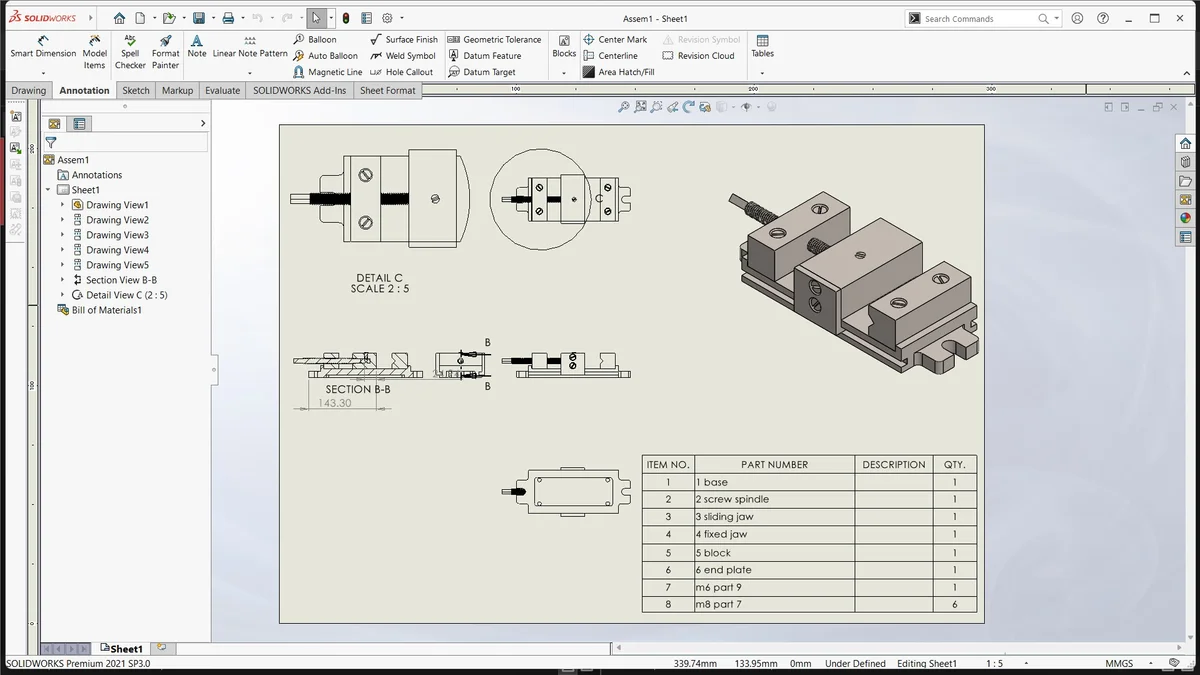
Machine Vise
SolidWorks
A classic machine design exercise. The base, screw spindle, sliding and fixed jaws, blocks and end plates were modelled as separate parts and assembled. The drawing sheet uses section and scaled detail views to reveal the internal screw mechanism, supported by a complete bill of materials.
Objectives
Model each vise component as a distinct part
Assemble the sliding and fixed jaw mechanism
Use section and detail views to show internals
Document the assembly with a full bill of materials
Deliverables
Vise assembly with 8 line items
Section and 2:5 detail views
Complete bill of materials
Process
Modelled base, jaws and blocks from dimensioned sketches
Built the screw spindle and end-plate features
Assembled and checked jaw travel and interference
Prepared section B-B, detail views and a BOM
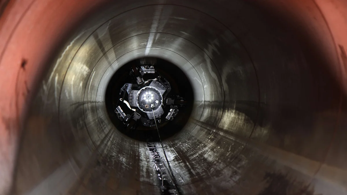
Inline Pipe Inspection Robot
SolidWorks
The project covered the full development cycle: concept selection, 3D CAD modelling, mechanism and drive design, material selection, detailed manufacturing drawings and hands-on fabrication. The robot travels through pipe sections while carrying an inspection module, with a focus on compact packaging and reliable travel.
Objectives
Design a compact robot that travels inside pipelines
Size a drive and support mechanism for pipe travel
Prepare detailed drawings for fabrication
Assemble and test a working prototype
Deliverables
Complete 3D CAD model and assembly
Manufacturing drawing set
Assembled working prototype
Process
Evaluated concepts and selected the drive arrangement
Sized the drive and support mechanism
Prepared detailed manufacturing drawings
Fabricated and tested the prototype
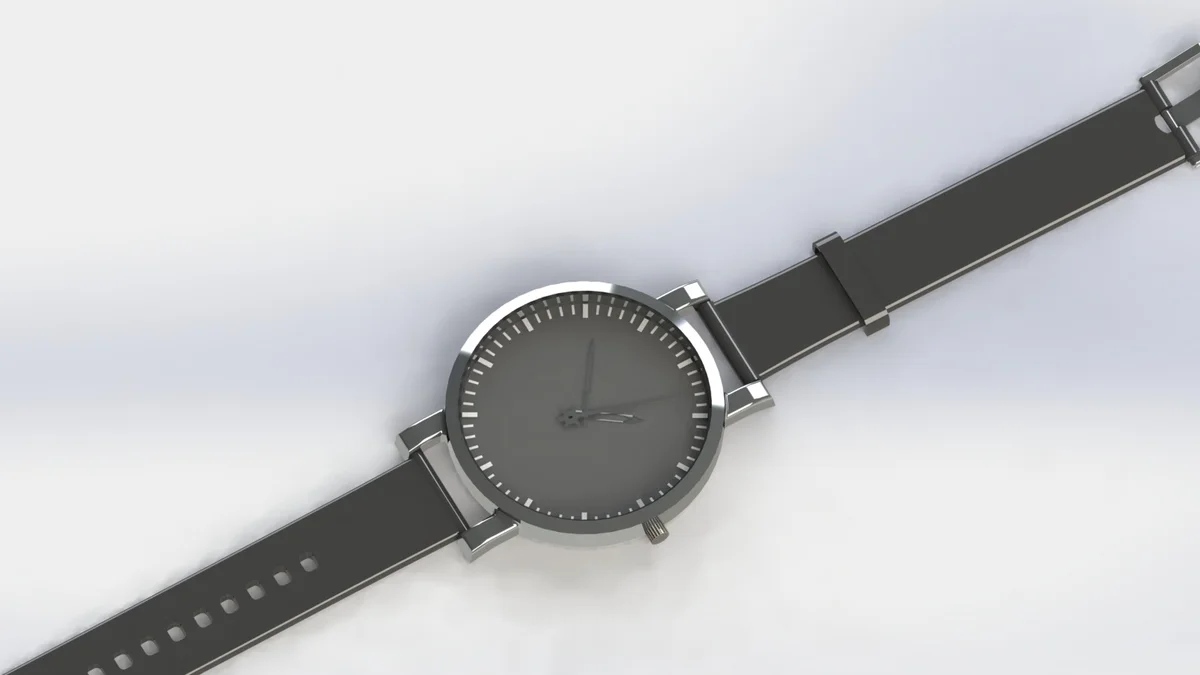
Wrist Watch Design
Creo
A product design exercise built from the case outward in Creo. Revolve and sweep features shaped the body and strap, dial detailing was modelled to scale, and realistic metal and matte finishes were applied to review form and proportion.
Objectives
Design a clean, minimal watch case and dial
Model a swept strap with buckle and adjustment holes
Apply realistic metal and matte finishes
Produce product renders for design review
Deliverables
Watch assembly model
Strap and buckle detail
Product render sheet
Process
Revolved the case body and bezel from a profile sketch
Modelled dial indices, hands and crown detail
Swept the strap and built the buckle assembly
Rendered with reflective and matte materials
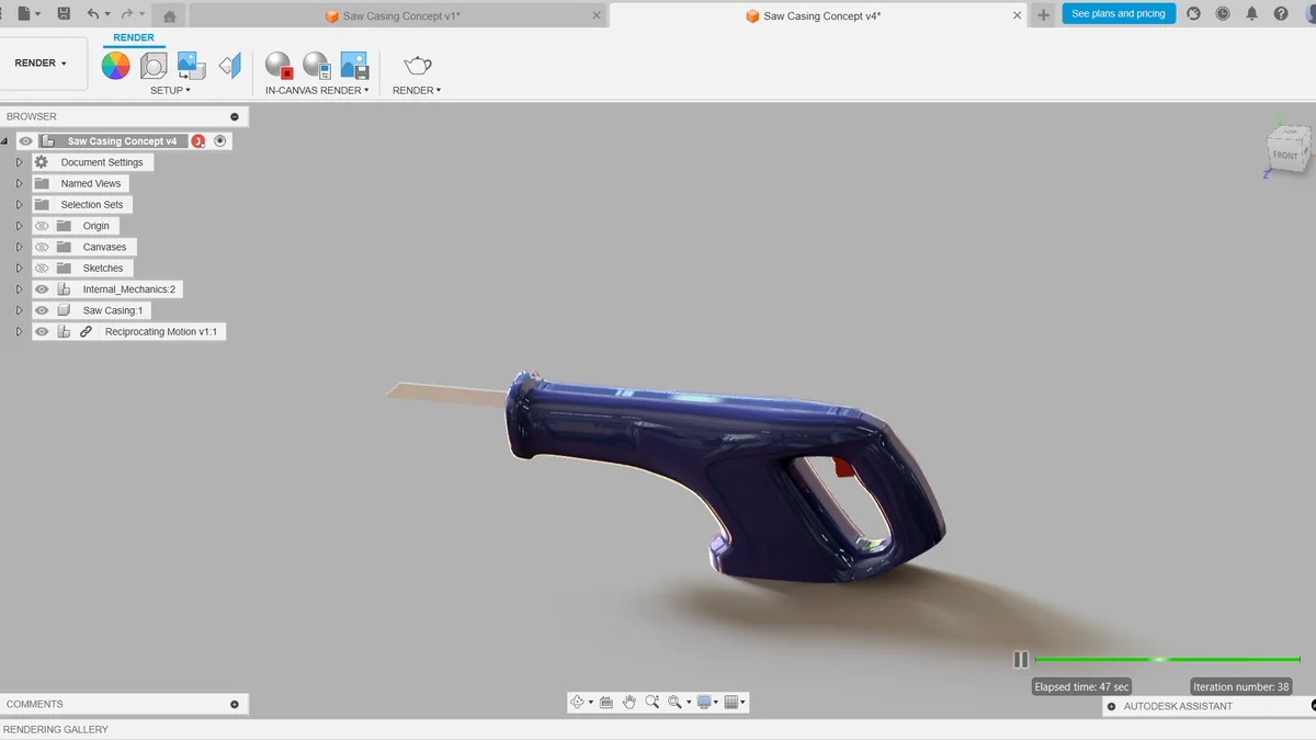
Reciprocating Saw Casing
Fusion 360
This project balanced form and function. The outer casing and handle were modelled for a comfortable grip, then combined with an internal mechanism and a reciprocating motion study so blade travel could be reviewed. Iterations from v1 to v4 refined the shell into the final render.
Objectives
Develop an ergonomic one-piece outer casing
Package an internal drive mechanism
Validate blade travel with a motion study
Iterate the concept from v1 to the final render
Deliverables
Casing shell model
Internal mechanism assembly
Reciprocating motion study
Final rendered presentation
Process
Sketched and modelled the casing shell and handle
Built the internal mechanism components
Ran a reciprocating motion study on blade travel
Refined the shell across four concept revisions
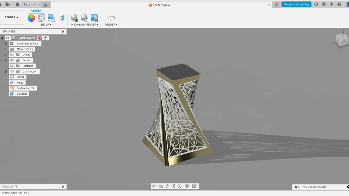
Twisted Lattice Lamp
Fusion 360
The lamp body was shelled from a revolve, then a twisting lattice was generated as a pipe structure following curved surface paths. A surface patch closed the form, balancing a solid body with an open lattice for a light, sculptural character.
Objectives
Shell a clean lamp body from a revolve
Generate a twisting lattice around the body
Close the surface form cleanly
Balance structure and light through the design
Deliverables
Lamp body model
Twisted lattice feature
Surface patch closure
Rendered presentation view
Process
Created the revolve and shelled the lamp body
Traced curved paths for the lattice structure
Built the lattice with a pipe along a path
Patched the surface and reviewed the render
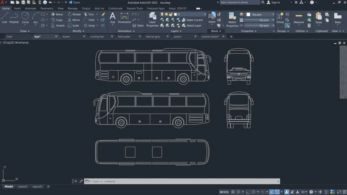
Bus Body 2D Drafting
AutoCAD
A 2D drafting exercise recreating a passenger bus as a full set of orthographic views in AutoCAD. Front, side and rear elevations were drawn alongside a plan view, using layer management and a consistent scale so every view aligns and reads like a real production drawing sheet.
Objectives
Draw accurate front, side and rear elevations of a bus body
Build an aligned plan (top) view
Use layers to separate outlines, details and hidden edges
Maintain clean linework and consistent scale across views
Deliverables
Four-view orthographic drawing set
Layered 2D wireframe model
Dimensioned and print-ready layout
Process
Drafted the side elevation including windows and wheel arches
Projected the front and rear views from reference lines
Added the plan view and checked alignment across all views
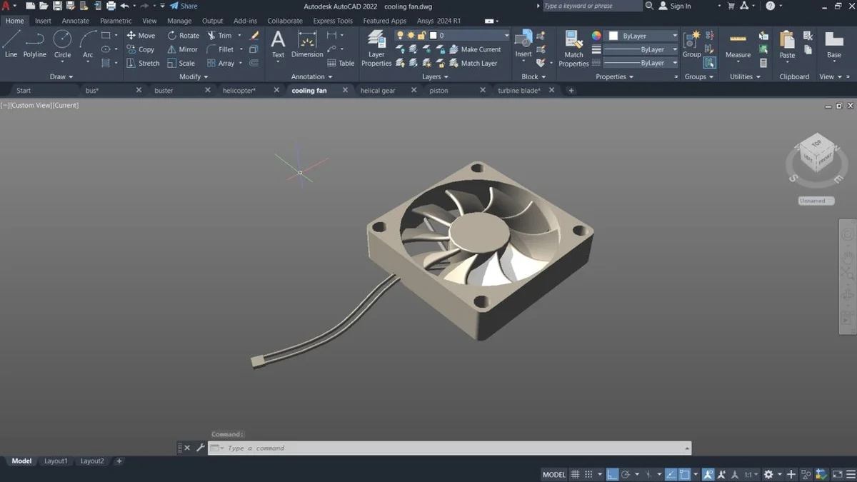
Cooling Fan 3D Model
AutoCAD
A 3D solid modelling exercise building a computer cooling fan in AutoCAD. The square mounting frame and corner fixings were modelled as solids, a multi-blade rotor was developed around a central hub, and the power cable was routed to complete the assembly before a shaded render was produced.
Objectives
Model the square fan housing with corner fixings
Develop a multi-blade impeller around a central hub
Route the power cable and connector detail
Produce a clean shaded render for presentation
Deliverables
Fan housing and rotor solids
Assembled 3D model with cable detail
Shaded presentation render
Process
Extruded the fan frame and cut the mounting holes
Sketched and patterned the rotor blades around the hub
Added the hub, shaft and cable detail
Rendered the assembly with realistic shading
Certifications
Solidworks
Creo
AutoCAD
Ansys
Fusion 360
